A couple of days ago, Cameron, a PyImageSearch reader emailed in and asked about methods to find the distance from a camera to an object/marker in an image. He had spent some time researching, but hadn’t found an implementation.
I knew exactly how Cameron felt. Years ago I was working on a small project to analyze the movement of a baseball as it left the pitcher’s hand and headed for home plate.
Using motion analysis and trajectory-based tracking I was able to find/estimate the ball location in the frame of the video. And since a baseball has a known size, I was also able to estimate the distance to home plate.
It was an interesting project to work on, although the system was not as accurate as I wanted it to be — the “motion blur” of the ball moving so fast made it hard to obtain highly accurate estimates.
My project was definitely an “outlier” situation, but in general, determining the distance from a camera to a marker is actually a very well studied problem in the computer vision/image processing space. You can find techniques that are very straightforward and succinct like the triangle similarity. And you can find methods that are complex (albeit, more accurate) using the intrinsic parameters of the camera model.
In this blog post I’ll show you how Cameron and I came up with a solution to compute the distance from our camera to a known object or marker.
Definitely give this post a read — you won’t want to miss it!
Looking for the source code to this post?
Jump right to the downloads section.
OpenCV and Python versions:
This example will run on Python 2.7/Python 3.4+ and OpenCV 2.4.X.
Triangle Similarity for Object/Marker to Camera Distance
In order to determine the distance from our camera to a known object or marker, we are going to utilize triangle similarity.
The triangle similarity goes something like this: Let’s say we have a marker or object with a known width W. We then place this marker some distance D from our camera. We take a picture of our object using our camera and then measure the apparent width in pixels P. This allows us to derive the perceived focal length F of our camera:
F = (P x D) / W
For example, let’s say I place a standard piece of 8.5 x 11in piece of paper (horizontally; W = 11) D = 24 inches in front of my camera and take a photo. When I measure the width of the piece of paper in the image, I notice that the perceived width of the paper is P = 248 pixels.
My focal length F is then:
F = (248px x 24in) / 11in = 543.45
As I continue to move my camera both closer and farther away from the object/marker, I can apply the triangle similarity to determine the distance of the object to the camera:
D’ = (W x F) / P
Again, to make this more concrete, let’s say I move my camera 3 ft (or 36 inches) away from my marker and take a photo of the same piece of paper. Through automatic image processing I am able to determine that the perceived width of the piece of paper is now 170 pixels. Plugging this into the equation we now get:
D’ = (11in x 543.45) / 170 = 35in
Or roughly 36 inches, which is 3 feet.
Note: When I captured the photos for this example my tape measure had a bit of slack in it and thus the results are off by roughly 1 inch. Furthermore, I also captured the photos hastily and not 100% on top of the feet markers on the tape measure, which added to the 1 inch error. That all said, the triangle similarity still holds and you can use this method to compute the distance from an object or marker to your camera quite easily.
Make sense now?
Awesome. Let’s move into some code to see how finding the distance from your camera to an object or marker is done using Python, OpenCV, and image processing and computer vision techniques.
Finding the distance from your camera to object/marker using Python and OpenCV
Let’s go ahead and get this project started. Open up a new file, name it distance_to_camera.py , and we’ll get to work.
|
1 2 3 4 5 6 7 8 9 10 11 12 13 14 15 16 17 |
# import the necessary packages import numpy as np import cv2 def find_marker(image): # convert the image to grayscale, blur it, and detect edges gray = cv2.cvtColor(image, cv2.COLOR_BGR2GRAY) gray = cv2.GaussianBlur(gray, (5, 5), 0) edged = cv2.Canny(gray, 35, 125) # find the contours in the edged image and keep the largest one; # we'll assume that this is our piece of paper in the image (cnts, _) = cv2.findContours(edged.copy(), cv2.RETR_LIST, cv2.CHAIN_APPROX_SIMPLE) c = max(cnts, key = cv2.contourArea) # compute the bounding box of the of the paper region and return it return cv2.minAreaRect(c) |
The first thing we’ll do is import our necessary packages. We’ll use NumPy for numerical processing and cv2 for our OpenCV bindings.
From there we define our find_marker function. This function accepts a single argument, image , and is meant to be utilized to find the object we want to compute the distance to.
In this case we are using a standard piece of 8.5 x 11 inch piece of paper as our marker.
Our first task is to now find this piece of paper in the image.
To to do this, we’ll convert the image to grayscale, blur it slightly to remove high frequency noise, and apply edge detection on Lines 7-9.
After applying these steps our image should look something like this:
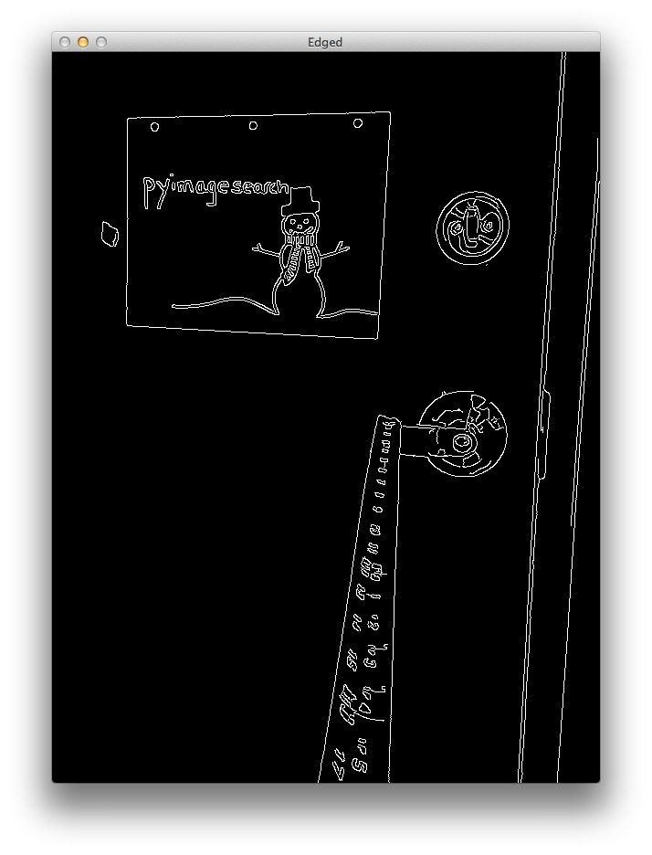
As you can see, the edges of our marker (the piece of paper) have clearly been reveled. Now all we need to do is find the contour (i.e. outline) that represents the piece of paper.
We find our marker on Line 13 by using the cv2.findContours function and then determining the contour with the largest area on Line 14.
We are making the assumption that the contour with the largest area is our piece of paper. This assumption works for this particular example, but in reality finding the marker in an image is highly application specific.
In our example, simple edge detection and finding the largest contour works well. We could also make this example more robust by applying contour approximation, discarding any contours that do not have 4 points (since a piece of paper is a rectangle and thus has 4 points), and then finding the largest 4-point contour.
Note: More on this methodology can be found in this post on building a kick-ass mobile document scanner.
Other alternatives to finding markers in images is to utilize color, such that the color of the marker is substantially different from the rest of the scene in the image. You could also apply methods like keypoint detection, local invariant descriptors, and keypoint matching to find markers; however, these approaches are outside the scope of this article and are again, highly application specific.
Anyway, now that we have the contour that corresponds to our marker, we return the bounding box which contains the (x, y)-coordinates and width and height of the box (in pixels) to the calling function on Line 17.
Let’s also quickly to define a function that computes the distance to an object using the triangle similarity detailed above:
|
19 20 21 |
def distance_to_camera(knownWidth, focalLength, perWidth): # compute and return the distance from the maker to the camera return (knownWidth * focalLength) / perWidth |
This function takes a knownWidth of the marker, a computed focalLength , and perceived width of an object in an image (measured in pixels), and applies the triangle similarity detailed above to compute the actual distance to the object.
To see how we utilize these functions, continue reading:
|
1 2 3 4 5 6 7 8 9 10 11 12 13 14 15 16 17 18 19 20 21 22 23 24 25 26 27 28 29 30 31 32 33 34 35 36 37 38 39 |
# import the necessary packages import numpy as np import cv2 def find_marker(image): # convert the image to grayscale, blur it, and detect edges gray = cv2.cvtColor(image, cv2.COLOR_BGR2GRAY) gray = cv2.GaussianBlur(gray, (5, 5), 0) edged = cv2.Canny(gray, 35, 125) # find the contours in the edged image and keep the largest one; # we'll assume that this is our piece of paper in the image (cnts, _) = cv2.findContours(edged.copy(), cv2.RETR_LIST, cv2.CHAIN_APPROX_SIMPLE) c = max(cnts, key = cv2.contourArea) # compute the bounding box of the of the paper region and return it return cv2.minAreaRect(c) def distance_to_camera(knownWidth, focalLength, perWidth): # compute and return the distance from the maker to the camera return (knownWidth * focalLength) / perWidth # initialize the known distance from the camera to the object, which # in this case is 24 inches KNOWN_DISTANCE = 24.0 # initialize the known object width, which in this case, the piece of # paper is 11 inches wide KNOWN_WIDTH = 11.0 # initialize the list of images that we'll be using IMAGE_PATHS = ["images/2ft.png", "images/3ft.png", "images/4ft.png"] # load the furst image that contains an object that is KNOWN TO BE 2 feet # from our camera, then find the paper marker in the image, and initialize # the focal length image = cv2.imread(IMAGE_PATHS[0]) marker = find_marker(image) focalLength = (marker[1][0] * KNOWN_DISTANCE) / KNOWN_WIDTH |
The first step to finding the distance to an object or marker in an image is to calibrate and compute the focal length. To do this, we need to know:
- The distance of the camera from an object.
- The width (in units such as inches, meters, etc.) of this object. Note: The height could also be utilized, but this example simply uses the width.
Let’s also take a second and mention that what we are doing is not true camera calibration. True camera calibration involves the intrinsic parameters of the camera, which you can read more on here.
On Line 25 we initialize our known KNOWN_DISTANCE from the camera to our object to be 24 inches. And on Line 29 we initialize the KNOWN_WIDTH of the object to be 11 inches (i.e. a standard 8.5 x 11 inch piece of paper laid out horizontally).
We then define the paths to our images we are going to use on Line 32.
The next step is important: it’s our simple calibration step.
We load the first image off disk on Line 37 — we’ll be using this image as our calibration image.
Once the image is loaded, we find the piece of paper in the image on Line 38, and then compute our focalLength on Line 39 using the triangle similarity.
Now that we have “calibrated” our system and have the focalLength , we can compute the distance from our camera to our marker in subsequent images quite easily.
Let’s see how this is done:
|
41 42 43 44 45 46 47 48 49 50 51 52 53 54 55 56 |
# loop over the images for imagePath in IMAGE_PATHS: # load the image, find the marker in the image, then compute the # distance to the marker from the camera image = cv2.imread(imagePath) marker = find_marker(image) inches = distance_to_camera(KNOWN_WIDTH, focalLength, marker[1][0]) # draw a bounding box around the image and display it box = np.int0(cv2.cv.BoxPoints(marker)) cv2.drawContours(image, [box], -1, (0, 255, 0), 2) cv2.putText(image, "%.2fft" % (inches / 12), (image.shape[1] - 200, image.shape[0] - 20), cv2.FONT_HERSHEY_SIMPLEX, 2.0, (0, 255, 0), 3) cv2.imshow("image", image) cv2.waitKey(0) |
We start looping over our image paths on Line 42.
Then, for each image in the list, we load the image off disk on Line 45, find the marker in the image on Line 46, and then compute the distance of the object to the camera on Line 47.
From there, we simply draw the bounding box around our marker and display the distance on Lines 50-56.
Results
To see our script in action, open up a terminal, navigate to your code directory, and execute the following command:
|
1 |
$ python distance_to_camera.py |
If all goes well you should first see the results of 2ft.png , which is the image we use to “calibrate” our system and compute our initial focalLength :

Figure 2: This image is used to compute the initial focal length of the system. We start by utilizing the known width of the object/marker in the image and the known distance to the object.
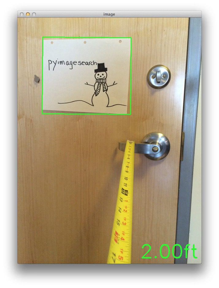
From the above image we can see that our focal length is properly determined and the distance to the piece of paper is 2 feet, per the KNOWN_DISTANCE and KNOWN_WIDTH variables in the code.
Now that we have our focal length, we can compute the distance to our marker in subsequent images:
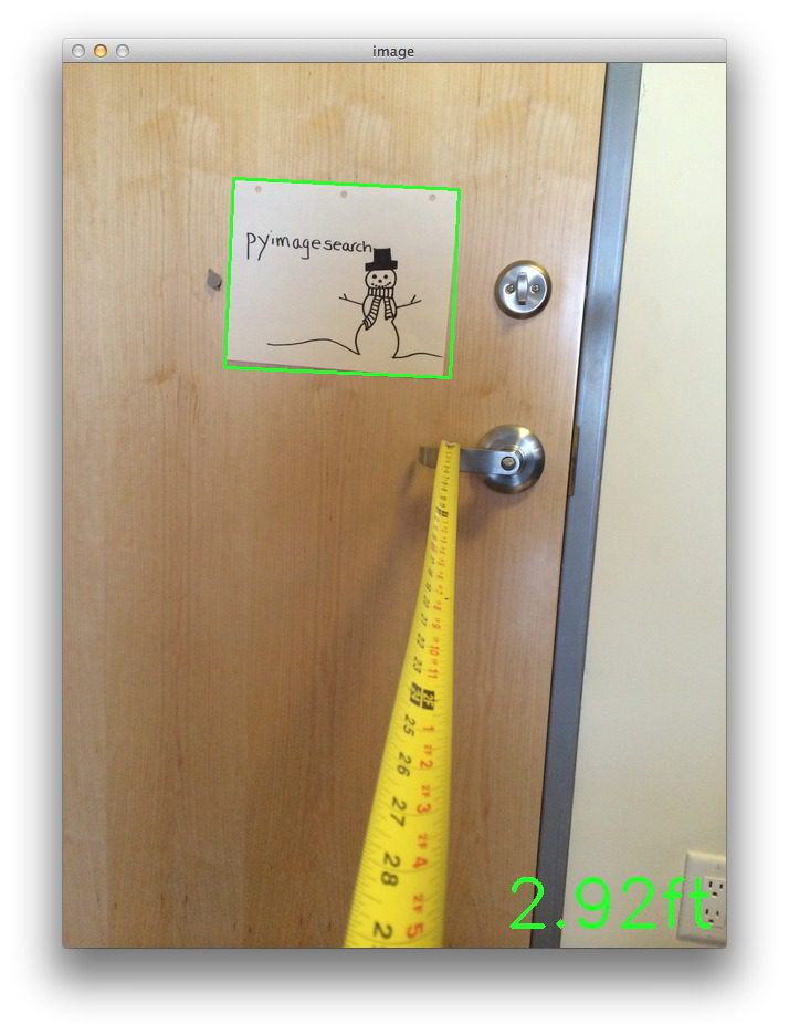
Figure 3: Utilizing the focal length to determine that our piece of paper marker is roughly 3 feet from our camera.
In above example our camera is now approximate 3 feet from the marker.
Let’s try moving back another foot:

Figure 4: Utilizing the computed focal length to determine our camera is roughly 4 feet from our marker.
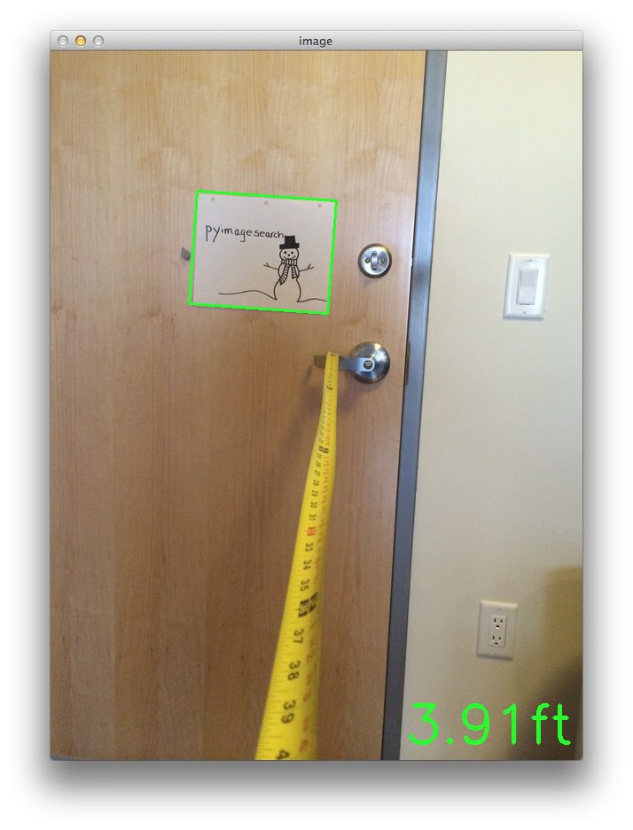
Again, it’s important to note that when I captured the photos for this example I did so hastily and left too much slack in the tape measure. Furthermore, I also did not ensure my camera was 100% lined up on the foot markers, so again, there is roughly 1 inch error in these examples.
That all said, the triangle similarity approach detailed in this article will still work and allow you to find the distance from an object or marker in an image to your camera.
Summary
In this blog post we learned how to determine the distance from a known object in an image to our camera.
To accomplish this task we utilized the triangle similarity, which requires us to know two important parameters prior to applying our algorithm:
- The width (or height) in some distance measure, such as inches or meters, of the object we are using as a marker.
- The distance (in inches or meters) of the camera to the marker in step 1.
Computer vision and image processing algorithms can then be used to automatically determine the perceived width/height of the object in pixels and complete the triangle similarity and give us our focal length.
Then, in subsequent images we simply need to find our marker/object and utilize the computed focal length to determine the distance to the object from the camera.


Good info here:
http://photo.stackexchange.com/questions/12434/how-do-i-calculate-the-distance-of-an-object-in-a-photo
How could you apply these techniques to sports events photos taken with a telephoto lens?
You would have to estimate the intrinsic parameters of the camera which requires calibration with a “chessboard”.
HI Adrian,
Nice post, I will try to implement the idea to determine the size of an object after the calibration.
Great article Adrian, it was really helpful! Thank you so much!
I’m glad you enjoyed it Hajar!
hey, Adrian
it’s a great piece of work you have done here and i used this technique working for my android device , and i want to take it to next level by measuring multiple object distances..but getting same results if two objects are on same position. any suggestions would be appreciated
thnx
Hi JD, if you are looking to measure multiple objects, you just need to examine multiple contours from the
cv2.findContoursfunction. In this example, I’m simply taking the largest one, but in your case, you should loop over each of the contours individually and process them and see if they correspond to your marker.on above example, we know the width of an object. What if we don’t know the width of the object ? for example in real life situation where a robot need to navigate the it meets each unknown object and need to find the distance even tough it has now knowledge about each objects actual width. Any other examples ?
In general, you’ll need to know the dimension of the object in order to get an accurate reading on the width/height. However, in unconstrained environments you might be able to use a stereo camera so you can compute the “depth” of an image and do a better job avoiding obstacles.
Is it possible to do this using the back end of a car in realtime? Maybe a HOG classifier could detect it and than the program? Any insight would be helpful.
Thanks
Take a look at this post on HOG + Linear SVM, I think it will really help you get started.
Hi there Andrian!
First of all i’m very thankful for this and other tutorials out there! this is by far the best series of tutorials online! Perfectly described step by step and explained why to preform every step
I can’t thank you enough!
I’m trying to do the same thing as described in the above tutorial (finding an object and determine the distance between obj and camera) but i wonder how i should do it when using constant streaming video instead of loading images?
thanks!
Hi Dries, thanks for the great comment, it definitely put a smile on my face
As for when using a constant video stream versus loading images, there is no real difference, you just need to update the code to use a video stream. It’s actually a lot easier than it sounds and I cover it both in Practical Python and OpenCV and this post.
what if i wanted to display cm instead of ft?
Your final metric is completely arbitrary — you can use feet, meters, centimeters, whatever you want. Take a look at Lines 25 and 29 and redefine them using the metric you want. And then you’ll need to modify Line 52 to output your metric instead of feet.
Hi there,
when i try the same code using 2 feet and an image of 1 inch ,the focal length is around 1260 . Is this ok ? coz im getting unacceptable distances of around 3.4 feet for 6 feet… Are there any limits for this method . I find this method really interesting , i am thinking forward to do this in my project .
One more thing , will this work for webcam from a laptop .
Thanks in advance
The main limitation of this method is that you need to have a straight-on view of the object you are detecting. As the viewpoint becomes angled, it distorts the calculation of the bounding box and thus the overall returned distance. And yes, this method will work with your laptop webcam, you just need to update the code to grab frames using the
cv2.VideoCapturefunction. See this post for an example of grabbing frames from the webcam stream.Hi Adrian, Excelent tutorial i have a question for you, i hope you can help me.
i need the position (X,Y,Z) in mm, with your tutorial i could get the point z, my problem is when i calibrate the camera to get the points X,Y my Z is wrong.
do you know what happens?
Thanks.
Are you doing work in 3D? If so, this method is not suited for 3D and you’ll need to use a different calibration method to examine the intrinsic parameters.
Hi Adrian, Thanks for answer me.
I’ll tell you what my project. I detect a small object in real time with a webcam, with the position of the object, will point a laser that will be about two servos , one for the X axis , and one for the Y axis.
I am ready the detection and tracking. but I’m having trouble getting the positions X , Y, Z . I research the transformation from 3D to 2D but there are certain points that do not understand.
do you can help me?
Thanks a lot
Hi David !
Currently, I’m working on a similar project, and I have a problem to do the relationship between coordinates in the 3D and servos. First, I would like to compute and track my 3D-coordinates object but it does not work.
Did you find an idea ?
Thanks
awesome program.but how to use it for a real streaming purpose.
This code can be easily adapted to work in real-time video streams. I would start by looking up the
cv2.VideoCapturefunction. I use it multiple times on the PyImageSearch blog — I think this post can help get you started.hi sir
i tried cv2.videocapture but ended with errors so i request you to modify the program
If you are getting errors related to
cv2.VideoCaptureyou should ensure that your installation of OpenCV has been compiled with video support.Hi Adrian, how do you define the marker?
In the case of this blog post, I defined a marker as a large rectangle. Rectangle-like regions have the benefit of being easy to find in an image. Markers can be made more robust by adding (1) color or (2) any type of special design on the marker themselves.
excuse me, I want to know how to realise it in real-time camera?
In order to perform real-time distance detection, you’ll need to leverage the
cv2.VideoCapturefunction to access the video stream of your camera. I have an example of accessing the video stream in this post. I also cover accessing the video stream more thoroughly inside Practical Python and OpenCV.Hi , this is a great helpful job
please i’m working on application that take an image then find the object to calculate its dimensins , so i need to know the distance or if there is another blog/ article/ refferance you can help me with
In order to compute the distance to an object in an image, you need to be able to identify what the object is. For example, you could maintain a know database of objects and their dimensions, so when you find them, just pull out the dimensions and run the distance calculation.
Thanks for your nice post.. it is really a good job.. dear, is there any additional procedure for which i can use this procedure for the unknown object distance measurement from camera….
You’ll need to know the size of some object in the image to perform camera calibration. In this example, we have a piece of paper. But you could have used a coin. A coffee cup. A book. But the point is that you need to know the size of object(s) you’ll be using to perform the camera calibration using triangle similarity.
Hi, Thank you for this post.
I’m looking for like Johnny Chung Lee’s Wii headtracking in VR Juggler through VRPN projects.
Anyway,
when I tried this code, there are some isues.
My pi2 connected with noir-picam and ms-webcam.
1. X-window
(image:1297): GdkGLExt-WARNING **: Window system doesn’t support OpenGL.
2. X-wondow with cv virtualenv
Traceback (most recent call last):
File “distance_to_camera.py”, line 41, in
marker = find_marker(image)
File “distance_to_camera.py”, line 16, in find_marker
(cnts, _) = cv2.findCountours(edged.copy(), cv2.RETR_LIST, cv2.CHAIN_APPROX_SIMPLE)
ValueError: too many values to unpack (expected 2)
3. console
(image:867): Gtk-WARNING **: cannot open display:
4. cv virtualenv
same with 2.
Please let me know the reason…
Hey Minjae:
1. I’m not a Windows user, so I’m not sure a about this particular problem. Perhaps another PyImageSearcher reacher can help you out here.
2. The code associated with this post was built for OpenCV 2.4. You are using OpenCV 3. You need to update the
cv2.findContoursfunction call, here to work with OpenCV 3..3. Are you SSH’ing into your Pi? If so, make sure you pass in the
-Xflag for X11 forwarding.Hi adrian,
Thanks for sharing.
I have tried your code and its work.
But is it possible to calculate the object distance if the object size in real world ( width / height ) unknown? Just using internal camera parameter and object size in pixels..
Hey Nami, you might want to look into camera calibration and the intrinsic camera parameters.
Hi adrian,
So after we do camera calibration and get focal length ( fx, fy), principal point, etc. How can i measure the object distance? with object size in real world undefine..
Thanks..
You basically need to convert the “pixel points” to “real world” points, from there the distance between objects can be measured. This is something I’ll try to cover on PyImageSearch in the future, but in the meantime, this is a really good MATLAB tutorial that demonstrates the basics.
Hello Adrian. First of all , This is a great website. I have a question : Is this distance estimation can be done in real time processing applications. I mean I want to measure distance from an object(cicular and coorful) to my robot while the robot moving on a straight line. ı use a moderate camera with low resolution(usb cam).How should I do that
Yes, this can absolutely be done in real-time processing, that’s not an issue. As long as you perform the calibration ahead of time, you can certainly perform the distance computation in your video pipeline.
Thanks for the help and your fast reply man. Camera Calibration looks like complicated though. Cause I wiil look at an object from an angled position say 30 degree(initially) while I m moving on a straigt line the angle will increase. In each time. So I have to make sure that the object is almost middle in the frame to use above code?
Camera calibration (at least the calibration discussed in this post) is actually pretty straightforward. This post assumes you have a 90-degree straight-on view of the object. For angled positioning this approach won’t work well unless you can apply a perspective transform. You should look into more advanced camera calibration methods.
Got it. I’ll get right on it. Hope to meet you
Hi Adrian. Thanks for the good work, it’s the most concise guide to this topic that I have found!
By the way, what camera did you use for this project?
I am trying to implement it through raspberry pi board camera and it doesn’t seem to work…
I simply took photos using my iPhone for this post, but the code can work with either a built-in/USB webcam or the Raspberry Pi camera. If you’re having trouble getting your Raspberry Pi camera + code working, I suggest reading this post on accessing the Raspberry Pi camera.
Hello Adrian!
First of all, thank you for a wonderful tutorial as always. I am working on a similar project and need some help.
1. Is there a literature review available regarding all methods of depth estimation
withoutusing a stereo camera i.e. using only a normal single lens camera? If not, can you point me to resources – papers and hopefully implementations – about the state-of-the-art on this problem? I should mention that I am mainly interested in understanding the physics of the scene and not reconstructing per se. I haven’t been able to find any decent open implementations of these and that’s kind of sad.2. I am investigating the importance of head movements in animals(humans included) for depth perception and came across few decade old papers on the topic. Can you provide me references on how motion of camera affects detection of edges, depth estimation etc from a computer vision perspective? Aligning with point 1, I am looking for something on the lines of how one can estimate depth accurately by moving the single lens camera and detect edges and/or object boundaries by virtue of this movement. Methods like triangle similarity aren’t really helpful since they need an estimate of the original size of object/marker in question.
Please help me out with this and keep up the good work!
For both questions, my suggestion would be start off with this paper and follow the references. This paper is heavily cited in the CV literature and links to previous works that should also help you out.
I may be coming in a little for this post but Im having trouble with the code.
When I run it I get the following error. Can you please assist me with this.
By the wayI think you are doing an awesome job.
Please see my reply to Minjae above and read this post for more information.
Thanks for that clarification!
hello Adrian. it a very good work.
but can i ask question, how to implement stereo vision in this project?
I honestly don’t do much work in stereo vision, although that’s something I would like to cover in 2016. Once I get a tutorial going for stereo version, I’ll be sure to let you know!
i will be really please to hear the news from u…thnk u very much
Hi Adrian!
First off, kudos on making such a complex system seem so intuitive! It makes the process look so much less intimidating to us newbies (whether I’m able to follow along once my picam gets here is another story!)
My question for ya is this: assuming I can manage to follow along and get distance readings for my marker, how difficult would it be to add the code required to trigger an event on a device that the marker is mounted to? In my case, I am looking to vibrate a small motor when the tracked object is more than 10 feet away. Ideally, it would increase in intensity based on how much further the object gets from the camera. I know this would require some investment in more hardware, but does it sound like a plausible idea?
Thanks for posting this, and being so generous with helping out in the comments!
The short answer to your question is that it would be easy to implement this type of functionality. All you would need to do is wrap this code in a VideoStream rather than processing a single image. From there, you can make a check if the object is > 10 feet away. If it is, then you call your buzzer code.
In OpenCV 3, we must use cv2.boxPoints(marker) instead of cv2.cv.BoxPoints(marker).
You’re absolutely right Randy!
Hey Adrian, great work! This was very informative and well done. I have a quick question regarding the limitations of such an approach when using larger distances. For example, 30 feet. At this distance, a relatively small object may be represented by very few pixels right? I’m assuming the better the camera (with better resolution) the farther the range in which this approach can still be accurate. My question is whether my assumption is indeed correct?
Furthermore, I find that when I utilize this approach, the distance calculation sometimes fluctuates as the perceived width in pixels fluctuates. Could this be due to noise? And if so, what are some good techniques to reduce said noise? I’ve looked into the blur function in OpenCV, but I haven’t had much luck with that.
Thanks again for the website, it’s super helpful. Look forward to hearing from you. Thank you!
Indeed, that is correct. The farther away the object is and the smaller the resolution of the camera is, the less accurate the approximation will be. As for reducing noise, that is entirely dependent on the image data you are working with. Blurring is one way to reduce noise. You might also want to look into the segmentation process and ensure you are obtaining an accurate segmentation of the background from the foreground. This can be improved by tweaking Canny edge detection parameter, threshold values, etc.
hello, please hellp me can i run this with opencv 3.1.0 ?
Please see my response to “Tyrone” above — the only change needed for this code to run with OpenCV 3 is to modify the
cv2.findContours.Hello Adrian… i just wanted to know that how can i use this distance recognition technique to make a 2D map of a vertical wall(whose photo can be taken easily) to precisely know the position of doors windows and other stuffs on the wall and the distances between each other and their dimensions with certain accuracy……???
Hi Adbul — I’m not sure quite sure what you mean by a 2D map of a vertical wall, but if you want super precise measurements between doors, windows, etc., then I would suggest using a 3D/stereo camera instead of a 2D camera. This will give you much better results.
Hi Adrian,
Thanks for your tuto again. I have a question. What happened if you tilt the paper with an angle, with respect to the camera ? Does your algo consider it ?
Thanks.
Yes, even with the paper titled, this algorithm will still find the paper, provided that the paper is the largest contour area in the image. For a more robust algorithm for finding rectangular regions (and verifying that they indeed have 4 vertices), please see this post.
Ok, but for example, if you tilted your paper with an angle of 90 degrees, you do not detect a rectangle, so you do not know the distance between the object and the camera no?
Hey Matt, I’m not sure I understand your question — a rectangle has 4 vertices, no matter how you rotate it. An easy way to detect rectangles in an image is to simply use contour approximation, which I mentioned in my previous comment.
If you consider z the axis on which you compute the distance object-camera, x and y the additional axes, and if you rotate with an angle 90 degrees around x-axis or y-axis, your camera do not detect a rectangle but a straight line. So what happens in this case ?
Thanks.
Oh, you were referring to the z-axis, that was my mistake. In that case, you would need utilize a more advanced algorithm to detect your object. This blog post is primarily geared towards easily detectable objects and computing the distance.
Hi Adrian, i need to find the distance and cordinates of the red marker. I made the filter to see red color only but i have problem considering distance. I lose the “seeing” the red color after 10cm (the markers are 3 red circle diameter 10cm each in triangle formation). Im using raspberry pi 2 b+ and pi camera
How are you looking for the red color? Via color thresholding? If so, investigate the mask that is being generated from
cv2.inRangeand see if the red color region exists in the mask. If it does, then you’ll likely want to look at the contours being detected and see if red masked region is being returned.how to work when difference size of same object?
You normally would use a single reference object to calibrate your camera. Once you have the camera calibrated, you can detect the distances/object sizes of varying sizes. See this blog post for more information.
Hi Adrian
Thanks for your great information, just I have a question.
if you take a picture of a special object for example in the ceiling and you are required to know the distance of that object from the camera but not the perpendicular distance, what should we do?
In fact I know the exact location of the camera (x,y,z) and also the location of the object in the ceiling in terms of (x,y) but I do not know the z of the object. I want to measure z.
As you said I can measure the perpendicular distance between the camera an the object by taking a picture of the object, but I have to know the direct distance (not perpendicular) between the camera and the object.
Thank you so much
Hi dear Adrian . tanks for all of your good and useful information.I had very good result of this algorithm on mobile photography or raspberry camera . but i just have big problem with the digital camera witch has a lenses (DSLR or compact ). Can you help me about this?? if i know the F of the camera for example 3.2 how should be put it on my calculating ???
what i calculate (F) is about 3600~3700 . and so it’s give me wrong answer .
There is a difference between the focal length of the physical lens and the perceived focal length from the image. You’ll need to calibrate your DSLR camera in the same way that you performed the calibrations on the Pi and mobile phone.
Hello i am trying to use your code but not able to get output ,
getting error like..
Please help to resolve
Please read the comments to this post before you post as I’ve already addressed this issue multiple times. Since you’re using OpenCV 3, you need to change the
cv2.findContourscall to:(_, cnts, _) = cv2.findContours(edged.copy(), cv2.RETR_LIST, cv2.CHAIN_APPROX_SIMPLE)You can read more about the change to
cv2.findContoursbetween OpenCV 2.4 and OpenCV 3 in this blog post.Thank you!
Excellent article! But one little mistake that can confuse beginners, you wrote “perceived width of the paper is P = 249 pixels” but in calculations you used 248. Hope to see the tutorial on finding the distance to an randomly chosen object by using stereo-pair of cameras.
Thanks for pointing out the typo! I have corrected it now.
Please comment on how accurate can this method be, i.e mm cm or in inches etc. also if I want to find distance between two objects, how should I modify this code?
The level of accuracy depends on the resolution of your camera. The smaller the resolution, the less accurate. The further the objects are away, the less accurate. This script does not perform radial distortion correct, which is something else to consider. As for finding the distance between two objects, please see this post.
Hello Adrain,
Great Article to start with the distance estimation.
I have downloaded your code and trying to validate with images, but i am not getting the distance as expected. Could you please send me some reference images.
Hey Shiva — the downloads to this blog post also include the example images I included in this post. You can use these images to validate your distances.
Hai Adrian, when i try run the code, i got error :
Please, hope the resolve
The code for this blog post was intended for OpenCV 2.4; however, you are using OpenCV 3. You can resolve the issue by changing the code to:
box = cv2.boxPoints(marker)Hello Adrian Rosebrock,
Your explanation helped me understand the concept very well. I am still perplexed by another problem. For example, I have a calibrated camera, i.e. I know the focal lengths and the optical offsets of the lens and sensor. Then, the relation between pixel and the actual height/width of an object is true only if the object is placed at the focal length. If I place an object of unknown dimensions at an unknown distance from the camera lens, then there is no way to estimate the distance between them. Am I thinking right or is something missing? Can you please help.
Thanks
Hi. I was thinking about make mobile app which will measure width and height some objects by using dual cameras like this:www.theverge.com/2016/4/6/11377202/huawei-p9-dual-camera-system-how-it-works . Do you think that it will be working? Thank you for your answer.
Using two cameras you can measure the “depth” of an image. I don’t cover this on the PyImageSearch blog, but it is absolutely possible.
Hi Adrien,
Thanks for the information. I have one question: Is it possible to incorporate the distance estimation with the ball tracking code you have? I am currently working on a project whereby I am trying to detect an object with the color green and find the distance between the camera and the object.
Absolutely, but you need to calibrate your system first as I did in this blog post only this time using the green ball. From there you will be able to estimate distance.
Sorry, i seems to have phrased my question wrongly. What I meant was is it possible to find the distance from the camera to the green ball in real time? So instead of making it detect edges, i modified it to detect green?
Yes, it’s absolutely possible. As long as you perform the calibration step before you try to find the distances you can use the same technique to determine the distance to the ball in real-time.
Your help is greatly appreciated. Thank you.
Hello Adrian, nice post.
Just a simple question. How you determine the “focalLength”?
Take a look at the example in the “Triangle Similarity for Object/Marker to Camera Distance” section to see how focal length is computed. Otherwise,
Lines 38 and 39compute thefocalLengthvariable.Hello . I want to use this code to detect images real time using the PiCamera. I read your replies and honestly have no idea how to ” Use the cv2.VideoCapture function to access the stream of your camera ” . Playing with the code results in all sorts of errors. Could you help me by giving a detailed explanation ? Thanks
If you want to use the Raspberry Pi camera module you should start by reading this blog post on accessing the Pi camera module before doing anything else. From there, you can take the code from this post and use it with your Raspberry Pi camera.
Hi Adrain,
I am a big fan of your posts, I was impressed with all of what I have seen. I have a problem in my thesis that I guess you might help me in related to localization. My thesis project is automating the process of lawn mower. The mower will be given the size of a rectangle to cover then it will move back and forth starting from one of the corners. It will track its distance using wheel encoders, however, due to error due slippage and drifting. Therefore, we need a reliable method through which we can know the absolute location to correct for the relative localization error of wheel encoders. We have tried several methods and all had some problems:
1- Tracking successive features in frames to estimate the rotational and transnational matrices however for sharp turns it looses track of everything.
2- Triangulation by placing three balls of different colors and identifying the angle of each through a camera on a motor however using colors outdoor is so unreliable due different lightening at different day times. When you decrease the HSV scale becomes more accurate but increases the probability of loses balls and increasing range catches noise from the environment.
3- Using homography instead of color balls for triangulation but it is computationally slow.
4- Using April Tags or Aruco tags but as mechanical engineers, were are finding it hard to develop our algorithm and still we didn’t find a starting point to continue on by finding a code and understanding it.
Hope U can help us and sorry for the long post
To start, it’s always helpful to have actual real-world images of what you’re working with. This helps me and other readers visually see and appreciate what you are trying to accomplish. Myself, as I imagine many other readers, don’t know much about the intricacies of lawn mowers, wheel encoders, or slippage/drifting.
That said, based on your comment it seems that the homography is producing the correct results, correct? And if that’s the case why not focus your efforts on speeding up the homography estimation? Try to reduce the number of keypoints? Utilize binary rather than real-valued descriptors? Implement this part of the algorithm in C/C++ for an extra speed gain?
hi Adrian. Firstly,thank you for sharing.nowadays I am working similar projects.
so I have a question.there is an object with a known width w and I don’t know distance D from my camera.in fact I will do that I will put a rectangular object ( a box) with a known size under camera I will measure distance from object but I know only distance between camera and ground. how to do?
If you know the distance from the ground to the camera and know the size of the object in both units (inches, millimeters, etc.) then you should be able to apply some trigonometry to workout the triangle property. I haven’t actually tried this, so I’m just thinking off the top of my head. It might not work, but it’s worth a shot.
Hi Adrian, first of all, excellent article!
I have a question, regarding this code. I’m currently carrying out research for my dissertation which requires using stereo vision to calculate distance from the camera to a chosen object/area. Will this code be applicable for stereo vision as well ?
Thanks!
No, I would not use this code for stereo vision. The reason is because stereo cameras (by definition) can give you a much more accurate depth map. I don’t do much work in stereo vision, but this short tutorial or computing a depth map should help you out.
i am doing a project in which i need to get the exact location of a human at a distance. Exact location refers to the EXACT location as used by a gun to aim at an enemy. Here, i dont have any marker object or any known distances. Any way out?
You would need to compute the intrinsic properties of the camera first. I would suggest starting here.
Hey Adrian,
This is super nice tutorial ever!!
I am working on the project about detecting the distance changing of array sphere. (changing like mm in unit)
I gotta put the camera at the same axis of the movement so its very hard to see the difference.( the sphere is very small like 2 mm)
Do you think is it possible to detect using your algorithm?
It really depends on the quality of the images themselves. How high is the resolution of your image capture?
around 640 × 480 pixels/each image
for area of 1 x 2 cm
Hmm, that’s a pretty small resolution for that accurate of results. The first step would be to calibrate your camera and account for barrel distortion. If your images are really noisy and you can’t accurately segment the object from every image, then you’re in for some real trouble. But if you can get a nice segmentation I would give it a try and see what results you come up with. It’s best to experiment with projects like these and note what does and does not work.
Hi Adrian. i would like to calculate the distance between a drone flying at a good height (with a cam & MCUs) and people at the ground. Please help me Adrian. 😀
Hi Adrian.. your article is a really great tutorial 😀
btw i’m working on a project that measure distance of a fire, but fire tend to change it shape, whether it smaller or bigger, so the marker also get bigger or smaller, therefore I can’t define the width and height of the marker.
the question is, can I modify your algorithm so that I can measure distance with my condition ? or do you have another method that suitable to measure distance of a fire ?
Thanks in advance
Regards
Rahmat Hardian
It sounds like you might need a more advanced calibration technique. I personally haven’t done/read any research related to fire direction techniques with computer vision, but I would suggest reading up on intrinsic camera properties for calibration.